1. Introduction: The Enterprise Resiliency Challenge
In modern enterprise networks, WAN outages are not just an inconvenience—they are a direct threat to business operations. While many organizations successfully implement Dual-WAN SD-WAN to protect their public internet traffic, they often fail to extend that same resiliency to their private site-to-site communication.
If your HQ firewall has two internet connections, but your branch offices only have a single IPsec tunnel pointing to WAN1, a failure on that primary internet link will cut off your branch offices completely—even if your secondary WAN is healthy.
This comprehensive guide walks you through building a highly resilient Dual-WAN SD-WAN architecture with redundant, active-passive route-based IPsec VPN tunnels per branch. We will terminate these tunnels on a central FortiGate Hub and connect spokes running different operating systems: a Cisco IOS Router and a pfSense Firewall.
2. Architectural Blueprint & Topology
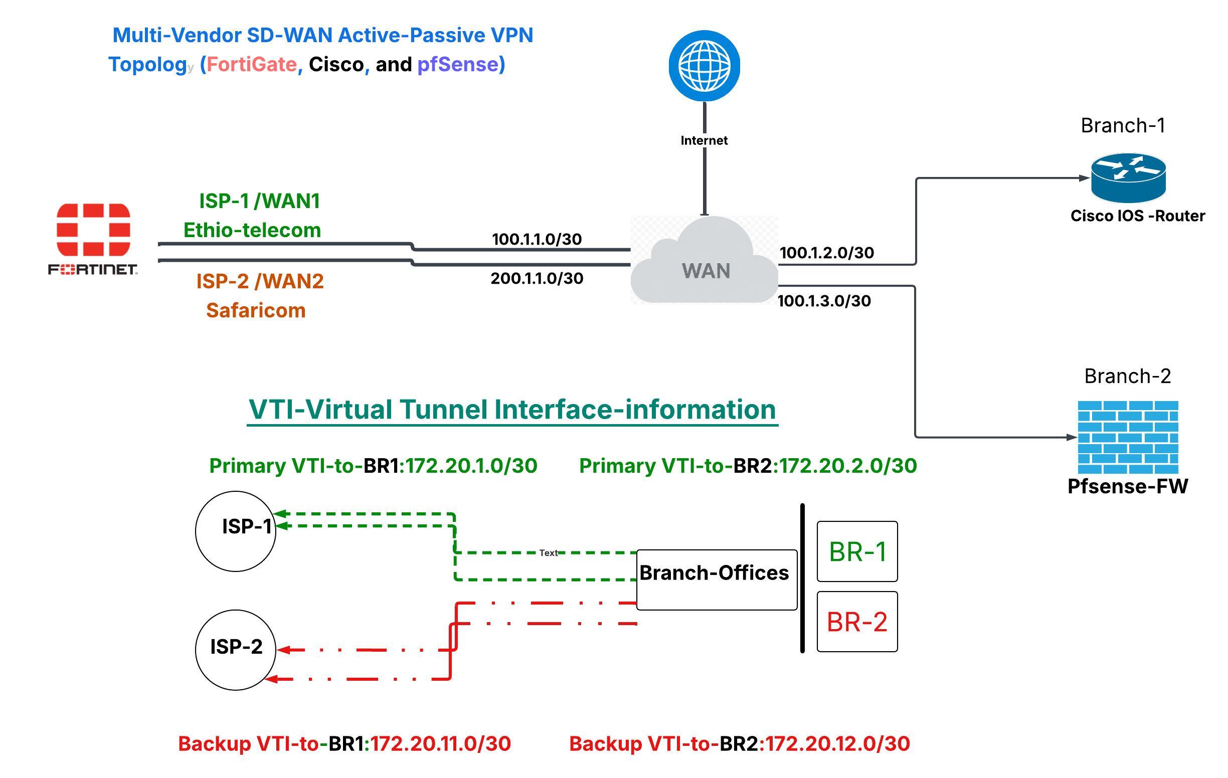
Here is our target topology. The FortiGate Hub manages two physical WAN connections. Each branch spoke maintains two concurrent, active-passive IPsec Virtual Tunnel Interfaces (VTIs): one over WAN1 (Primary) and one over WAN2 (Backup).
IP Addressing Table
| Device | Interface | Physical/Logical IP | Destination / Gateway |
|---|---|---|---|
| HQ-FortiGate | port1 (WAN1) | 100.1.1.2/30 | Gateway: 100.1.1.1 (Active) |
port4 (WAN2) | 200.1.1.2/30 | Gateway: 200.1.1.1 (Standby) | |
port2 (HQ LAN) | 10.10.0.1/24 | HQ Internal Subnet | |
| Branch 1 (Cisco) | WAN IP | 100.1.2.2 | Spoke WAN Gateway |
Tunnel1 (VTI-1) | 172.20.1.2/30 | Connects to HQ WAN1 (172.20.1.1) | |
Tunnel2 (VTI-2) | 172.20.11.2/30 | Connects to HQ WAN2 (172.20.11.1) | |
| Branch 2 (pfSense) | WAN IP | 100.1.3.2 | Spoke WAN Gateway |
VTIHQ (VTI-1) | 172.20.2.2/30 | Connects to HQ WAN1 (172.20.2.1) | |
VTIHQW2 (VTI-2) | 172.20.12.2/30 | Connects to HQ WAN2 (172.20.12.1) |
3. Phase 1: Configuring the SD-WAN Core on FortiGate
Before we can set up our backup VPN tunnels, we must transition our FortiGate Hub's physical interfaces (port1 and port4) into a logical SD-WAN Zone.
[!WARNING] When you add a physical port to a FortiGate SD-WAN zone, FortiOS will prevent the action if the interface is referenced in any static routes or firewall policies. You must delete or temporarily disable these references first, causing a brief window of downtime.
Step 3.1: Clean Up Existing References
- Navigate to Network → Static Routes and delete any default static routes pointing to
port1orport4. - Navigate to Policy & Objects → Firewall Policy and delete any internet access policies referencing
port1orport4directly (e.g.,HQ-LAN-to-Internetviaport2→port1).
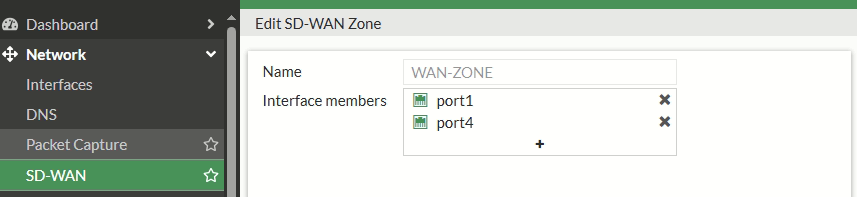
Step 3.2: Create the SD-WAN Zone and Add Members
- Go to Network → SD-WAN and select the SD-WAN Zones tab.
- Click Create New → SD-WAN Zone. Name it
WAN-ZONE. - Switch to the SD-WAN Members tab and click Create New → SD-WAN Member for both links:
-
Member 1 (WAN1):
- Interface:
port1 - SD-WAN Zone:
WAN-ZONE - Gateway:
100.1.1.1 - Priority:
1(Lower number = preferred active path)
- Interface:
-
Member 2 (WAN2):
- Interface:
port4 - SD-WAN Zone:
WAN-ZONE - Gateway:
200.1.1.1 - Priority:
10(Higher number = standby path)
- Interface:
Step 3.3: Point the Default Route to the SD-WAN Zone
Rather than configuring multiple default routes, point a single static route to the SD-WAN logical interface. SD-WAN will automatically handle the routing decisions based on link quality.
config router static
    edit 1
        set dst 0.0.0.0 0.0.0.0
        set device "SD-WAN"
        set comment "Default route pointing to the SD-WAN Zone"
    next
end
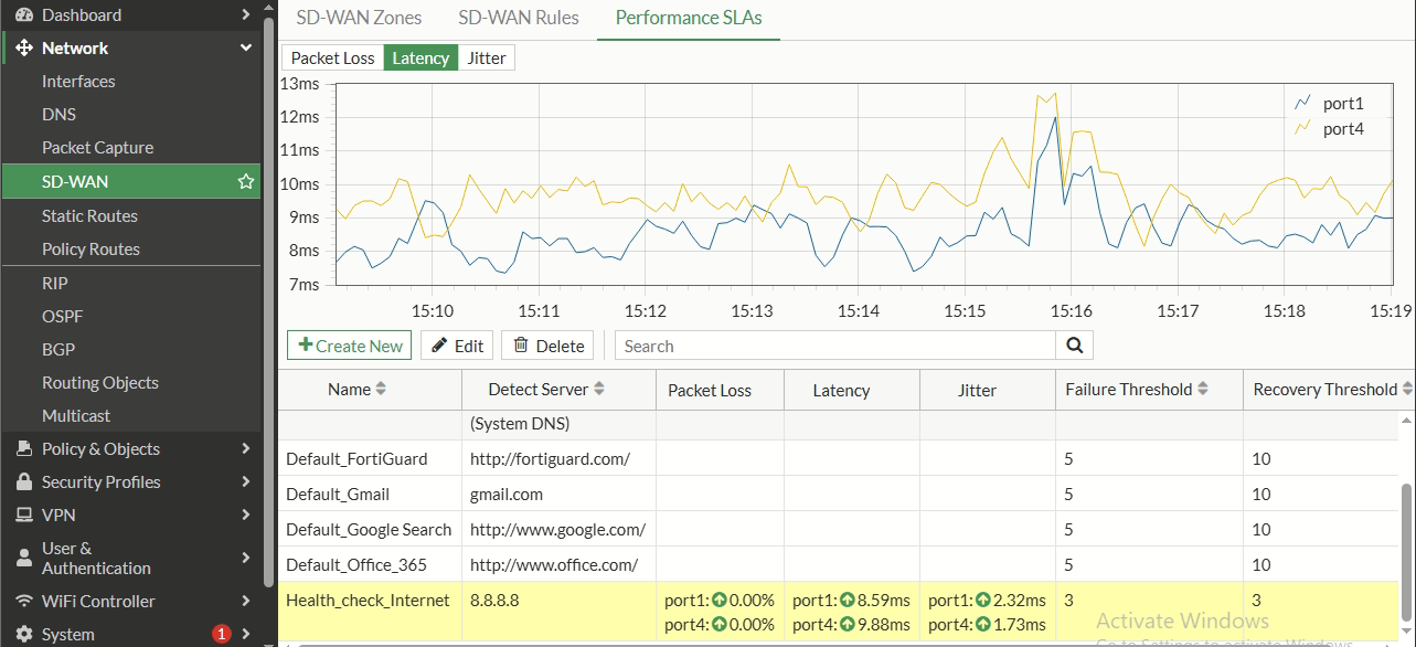
Step 3.4: Configure the Performance SLA (Health Link Check)
To dynamic failover, the FortiGate must actively monitor both WAN interfaces. We will configure an active ping probe targeting a reliable internet address (8.8.8.8).
- Navigate to Network → SD-WAN → Performance SLA and click Create New.
- Name:
HEALTH-CHECK-INTERNET - Protocol:
Ping - Server:
8.8.8.8 - Participants: Specify and select both
port1andport4. - Set the check interval to 500 ms with a failure count of 3 and restore count of 3.
Step 3.5: Configure Active-Passive Traffic Steering
Create an SD-WAN rule to keep all internet traffic on WAN1, shifting to WAN2 only if WAN1 fails the Performance SLA.
- Navigate to Network → SD-WAN → SD-WAN Rules and click Create New.
- Name:
DEFAULT-WAN-STEERING - Source/Destination:
all - Strategy:
Manual - Interface Preference: Add
port1first (Active), thenport4(Standby).
Step 3.6: Recreate Firewall Policies for SD-WAN
Now, recreate your outbound internet policy using the logical WAN-ZONE interface.
config firewall policy
    edit 100
        set name "HQ-LAN-to-Internet-SDWAN"
        set srcintf "port2"
        set dstintf "WAN-ZONE"
        set srcaddr "HQ-LAN"
        set dstaddr "all"
        set action accept
        set schedule "always"
        set service "ALL"
        set nat enable
        set comment "HQ LAN Internet access via SD-WAN Zone"
    next
end
4. Phase 2: Building Redundant IPsec VPN Tunnels (Hub-Side)
Now that the SD-WAN core is established, we will configure the backup IPsec tunnels on the FortiGate Hub to listen on port4 (WAN2). We will use Branch 1 (Cisco Spoke) as our reference.
Step 4.1: Configure Phase 1 & Phase 2 on the Backup Interface
We must create a custom IPsec tunnel bound to the WAN2 physical interface (port4), targeting the Spoke's public IP (100.1.2.2).
config vpn ipsec phase1-interface
    edit "VPN-BR1-W2"
        set type static
        set interface "port4"
        set ike-version 2
        set remote-gw 100.1.2.2
        set peertype any
        set net-device enable
        set proposal aes256-sha256
        set dhgrp 14
        set keylife 86400
        set psksecret NETLAB-HUB-HQ-BR1-AES256M513*
        set dpd on-demand
        set dpd-retrycount 5
        set dpd-retryinterval 30
        set comment "VPN Spoke 1 via Backup WAN2 (port4)"
    next
end

config vpn ipsec phase2-interface
    edit "VPN-BR1-W2-P2"
        set phase1name "VPN-BR1-W2"
        set proposal aes256-sha256
        set dhgrp 14
        set pfs enable
        set keylifeseconds 3600
        set auto-negotiate enable
        set comment "Phase2 Spoke 1 via Backup WAN2"
    next
end
Step 4.2: Assign VTI Tunnel IPs
Assign the designated tunnel IP address to the new virtual interface.
[!TIP] In FortiOS, it is best practice to assign VTI interfaces
/32subnet addresses while specifying a remote-ip destination. This avoids logical address overlap issues.
config system interface
    edit "VPN-BR1-W2"
        set ip 172.20.11.1/32
        set remote-ip 172.20.11.2/32
        set allowaccess ping
        set description "Tunnel-to-BR1-via-WAN2"
    next
end
Step 4.3: Configure the Backup Static Route with High Distance
Because we want the primary tunnel (VPN-BR1) to carry traffic under normal conditions, we must configure our routing table to prefer the primary path.
- If you are using static routes, set the administrative distance of the backup path higher (e.g., 200) than the primary route (default 10).
- If you are running OSPF, configure the backup static route with a distance higher than 110 (e.g., 200) so OSPF dynamic routes are always preferred.
config router static
    edit 20
        set dst 10.10.1.0 255.255.255.0
        set device "VPN-BR1-W2"
        set distance 200
        set comment "Backup route to Branch 1 LAN via WAN2 Tunnel"
    next
end
Step 4.4: Add Firewall Policies for the Backup Tunnel
Create the corresponding firewall rules to allow traffic to flow in both directions through the backup VTI interface.
config firewall policy
    edit 12
        set name "HQ-to-BR1-W2"
        set srcintf "port2"
        set dstintf "VPN-BR1-W2"
        set srcaddr "HQ-LAN"
        set dstaddr "BR1-LAN"
        set action accept
        set schedule "always"
        set service "ALL"
        set nat disable
    next
    edit 13
        set name "BR1-to-HQ-W2"
        set srcintf "VPN-BR1-W2"
        set dstintf "port2"
        set srcaddr "BR1-LAN"
        set dstaddr "HQ-LAN"
        set action accept
        set schedule "always"
        set service "ALL"
        set nat disable
    next
end
5. Phase 3: Branch Spokes Configuration (Cisco & pfSense)
For true end-to-end failover, the remote branch devices must be configured with a matching backup tunnel pointing to the HQ WAN2 public IP address (200.1.1.2).
5.1: Cisco IOS Spoke Configuration
On the Cisco IOS Spoke router (Gotera-BR-1), keep Tunnel1 pointing to the primary Hub WAN, and create Tunnel2 targeting the backup Hub WAN.
! --- Step 5.1.1: Create Keyring & IKEv2 Profile for WAN2 Hub
crypto ikev2 keyring KR-HQ-W2
 peer HQ-WAN2
  address 200.1.1.2
  pre-shared-key NETLAB-HUB-HQ-BR1-AES256M513*

crypto ikev2 profile PROF-IKEV2-HQ-W2
 match identity remote address 200.1.1.2 255.255.255.255
 identity local address 100.1.2.2
 authentication local pre-share
 authentication remote pre-share
 keyring local KR-HQ-W2
 dpd 30 5 on-demand

! --- Step 5.1.2: Create IPsec Profile for WAN2
crypto ipsec profile IPSEC-PROF-VTI-W2
 set ikev2-profile PROF-IKEV2-HQ-W2
 set transform-set TS-AES256-SHA256

! --- Step 5.1.3: Define Backup VTI Tunnel Interface
interface Tunnel2
 description Tunnel-to-HQ-via-WAN2-Backup
 ip address 172.20.11.2 255.255.255.252
 tunnel source GigabitEthernet0/0
 tunnel mode ipsec ipv4
 tunnel destination 200.1.1.2
 tunnel protection ipsec profile IPSEC-PROF-VTI-W2
 ip tcp adjust-mss 1360

! --- Step 5.1.4: Add Backup Static Route to HQ LAN (AD: 200)
ip route 10.10.0.0 255.255.255.0 Tunnel2 200
5.2: pfSense Spoke Configuration (The Gateway Group Strategy)
Unlike enterprise routers, pfSense does not natively support prioritizing static route distances via the GUI. Both VTIs would default to active routing paths. To enforce clean active-passive failover, we will leverage pfSense Gateway Groups.
  [LAN Traffic destination HQ] ──> [Firewall Rule] ──> [HQ-FAILOVER Gateway Group]
                                                               │
                                             ┌─────────────────┴─────────────────┐
                                             ▼                                   ▼
                                     [VTIHQ (Tier 1)]                   [VTIHQW2 (Tier 2)]
Step 5.2.1: Configure Phase 1 & Phase 2 Tunnels
- Go to VPN → IPsec → Tunnels and add a second Phase 1 entry:
- Connection Method: Start on demand
- Gateway IP:
200.1.1.2(HQ WAN2 IP) - Pre-Shared Key:
NETLAB-HUB-HQ-BR2-AES256M513*
- Create a Phase 2 under the new entry:
- Mode: Routed (VTI)
- Local IP:
172.20.12.2/30 - Remote IP:
172.20.12.1/30
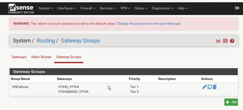
Step 5.2.2: Define Gateway Group for Failover
- Navigate to System → Routing → Gateways and confirm both VTI interfaces are listed as functional gateways.
- Switch to the Gateway Groups tab and click Add.
- Group Name:
HQ-FAILOVER - Set the member gateways:
VTIHQ_Gateway(WAN1) → Tier 1 (Preferred)VTIHQW2_Gateway(WAN2) → Tier 2 (Backup, only fires if Tier 1 is down)
- Trigger Level:
Member Down - Click Save and Apply Changes.
Step 5.2.3: Enforce Gateway Group via Policy Routing
Now, override standard routing by forcing traffic destined for HQ to use the Gateway Group.
- Navigate to Firewall → Rules → LAN and click Add (put at the top of the list).
- Action:
Pass - Protocol:
Any - Source:
LAN net(or10.10.2.0/24) - Destination:
10.10.0.0/24(HQ LAN) - Expand Advanced Options and scroll to Gateway.
- In the dropdown, select
HQ-FAILOVER. - Save and apply.
6. Verification & End-to-End Failover Testing
With the configurations in place, it is time to validate that our redundant architecture operates correctly.
Step 6.1: Verify Normal Operations (Both Tunnels UP)
On the FortiGate CLI, check the status of your VPN SAs. Both WAN1 and WAN2 tunnels should show active, established sessions.
get vpn ipsec tunnel summary
Expected Output:
'VPN-BR1' 100.1.1.2:500  ->  100.1.2.2:500  SA: temp-1  state: est
'VPN-BR1-W2' 200.1.1.2:500  ->  100.1.2.2:500  SA: temp-2  state: est
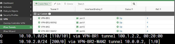
Verify that the active traffic path is routing through the primary tunnel:
get router info routing-table static | grep 10.10.1
Expected Output:
S 10.10.1.0/24 [10/0] device VPN-BR1
(The backup route to VPN-BR1-W2 is loaded into database but not active in the routing table due to its higher administrative distance of 200).
Step 6.2: Execute the Outage Test
To simulate a WAN outage on your primary provider, bring down the physical WAN1 interface on the FortiGate Hub.
config system interface
    edit port1
        set status down
    next
end
Now, monitor a continuous ping from a HQ host (10.10.0.10) to the branch LAN (10.10.1.10):
ping 10.10.1.10 -t
What happens under the hood during the transition:
- 0–3 Seconds: The primary WAN interface goes down. Pings briefly stop responding.
- 5 Seconds: The FortiGate DPD (Dead Peer Detection) detects the peer is dead over the primary link. The
VPN-BR1interface goes down. - 10 Seconds: The primary static route via
VPN-BR1is pulled from the routing table. - 12 Seconds: The standby route via
VPN-BR1-W2(AD 200) is promoted to the routing table. - 15 Seconds: Pings recover automatically, routing through WAN2.
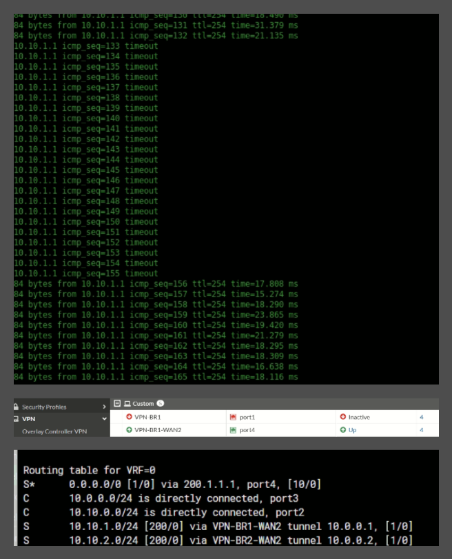
Verify that the backup routing table has active status on the secondary interface:
get router info routing-table all | grep 10.10.1
Expected Output:
S 10.10.1.0/24 [200/0] device VPN-BR1-W2
Step 6.3: Recover and Fallback
Once the primary ISP is online, bring the physical interface back up.
config system interface
    edit port1
        set status up
    next
end
The FortiGate will detect the link, establish VPN-BR1, and automatically swap the routing tables back since the primary route's distance of 10 is preferred over the backup's 200. Traffic will cleanly fall back to the primary path.
7. Senior Engineer's Summary: Best Practices
Deploying redundant topologies in production requires careful planning. Here are three key architectural takeaways from this implementation:
- Keep Cryptography Symmetric: Make sure your primary and backup tunnels use identical cryptographic settings (IKE versions, DH groups, cipher suites). A difference in Phase 2 ciphers can result in tunnels that fail to establish when a failover occurs.
- Watch your MTU/MSS settings: Encapsulating IP packets inside IPsec adds significant overhead. Make sure to apply MSS clamping (
ip tcp adjust-mss 1360on Cisco and equivalent settings on FortiGate/pfSense) to prevent fragmented packets from degrading network performance over VTIs. - Prefer Route-Based Over Policy-Based: Route-Based VTIs are vastly superior for redundancy. They allow you to apply dynamic routing or administrative distances cleanly without managing dozens of complex Phase 2 selectors and firewall rules.